
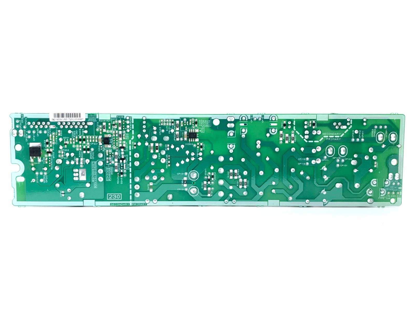
Power board assembly is the process of building the printed circuit boards that convert, regulate, and distribute electrical power inside electronic equipment. Unlike signal boards that mainly carry data, a power board must handle high currents and voltages safely, so every stage of its assembly is shaped by thermal, electrical, and mechanical demands. From industrial motor drives and telecom rectifiers to consumer chargers and medical devices, the reliability of the whole product often rests on the quality of its power board.
The process begins with design for manufacturing. Engineers choose board materials, copper weights, and layer counts based on current ratings and heat dissipation needs. Heavy copper, often two ounces per square foot or more, is common where traces must carry tens of amps without overheating. Wide traces, generous clearances, and carefully placed thermal vias help spread heat away from switching transistors, diodes, and transformers before a single component is placed.
Component selection is equally important. Power semiconductors such as MOSFETs, IGBTs, and rectifier diodes are chosen for voltage rating, on-state losses, and switching speed, while capacitors and inductors are sized for ripple current and energy storage. Engineers also consider derating, which means operating parts well below their maximum ratings so the board survives voltage spikes, temperature swings, and years of continuous use without premature failure.
Once the design is ready, fabrication produces the bare board. Copper layers are etched, drilled, and plated, and a solder mask protects the traces while a silkscreen marks component positions. For power boards, plated through holes and thick copper plating are especially important because they carry current between layers and provide mechanical strength for heavy parts such as transformers, chokes, and large electrolytic capacitors.
Assembly itself usually starts with solder paste printing. A stencil deposits a precise volume of paste onto each pad, and automated pick-and-place machines then position surface-mount components with high accuracy. For power boards, paste volume matters more than usual: too little paste creates weak joints under heavy parts, while too much can bridge closely spaced pins on power integrated circuits and cause short circuits.
Reflow soldering follows. The board passes through a temperature-controlled oven where the paste melts, wets the component leads, and forms solid joints. Power boards present a special challenge here because large copper planes absorb heat, so the reflow profile must be tuned to bring heavy sections up to temperature without overheating small, heat-sensitive parts elsewhere on the board.
Many power boards also need through-hole assembly. Large connectors, terminal blocks, and heat sinks are inserted into plated holes and soldered by wave soldering or selective soldering. These joints must withstand mechanical stress from cables and vibration, so inspection focuses on complete hole fill and strong fillets rather than appearance alone.
Thermal management continues after soldering. Heat sinks are attached with thermal paste or adhesive pads, and in some designs the board itself is bonded to a metal baseplate that spreads heat to an enclosure. Engineers verify thermal performance with infrared imaging and temperature sensors, checking that no component exceeds its rated temperature at full load and maximum ambient temperature.
Testing is where power board assembly proves itself. In-circuit testing checks for shorts, opens, and correct component values, while functional testing powers the board under load and measures output voltage, ripple, efficiency, and protection behavior. Overcurrent, overvoltage, and overtemperature protection circuits are deliberately triggered to confirm they respond before a fault can damage the board or the equipment it powers.
Safety and compliance testing are equally rigorous. High-voltage sections require isolation barriers, creepage and clearance distances, and insulation that meets the standards of the target market. Hipot testing applies a high voltage between isolated sections to confirm that the insulation holds, and the results are recorded as part of the board’s quality documentation.
Conformal coating or potting is often added for boards that will work in harsh environments. A thin protective coating shields the assembly from moisture, dust, and chemical exposure, while potting compound can secure heavy components against vibration. Both treatments must be applied carefully so they do not trap heat or interfere with connectors, trimmers, and other parts that need access after assembly.
Finally, documentation and traceability close the loop. Each production batch records component lots, solder materials, test results, and any rework performed. This record allows manufacturers to trace a field failure back to its cause, improve future builds, and give customers confidence that every power board leaving the factory meets the same standard as the one that passed qualification testing.
Before full production, a prototype run validates the design. Engineers assemble a small batch, measure efficiency and thermal behavior, and compare the results against simulation. Problems found at this stage, such as a noisy layout or an undersized inductor, are far cheaper to fix than after tooling and volume orders are committed, so prototype review is treated as a formal gate rather than a formality.
Inspection runs throughout assembly. Automated optical inspection checks component placement, polarity, and solder quality, while X-ray inspection reveals hidden joints under large packages such as ball grid arrays and power modules. Any board that fails inspection goes to a rework station where trained technicians repair joints under microscopes, and the board is tested again before it moves forward.
Sourcing also shapes assembly quality. Power components often have long lead times and strict authenticity requirements, so manufacturers buy from authorized distributors and verify incoming parts against their datasheets. Planning for component lifecycle matters too: a power board designed for a ten-year product life needs parts that will remain available, or a documented second source, so production is not stranded by a single discontinuation.
Looking ahead, power board assembly continues to evolve as wide-bandgap semiconductors such as gallium nitride and silicon carbide allow higher switching frequencies and smaller magnetics. These materials promise more efficient and compact power boards, but they also demand tighter layout control and new assembly techniques, keeping power board manufacturing a discipline where electrical design and factory process advance together.
